2021-L3-Galilee-Roobs
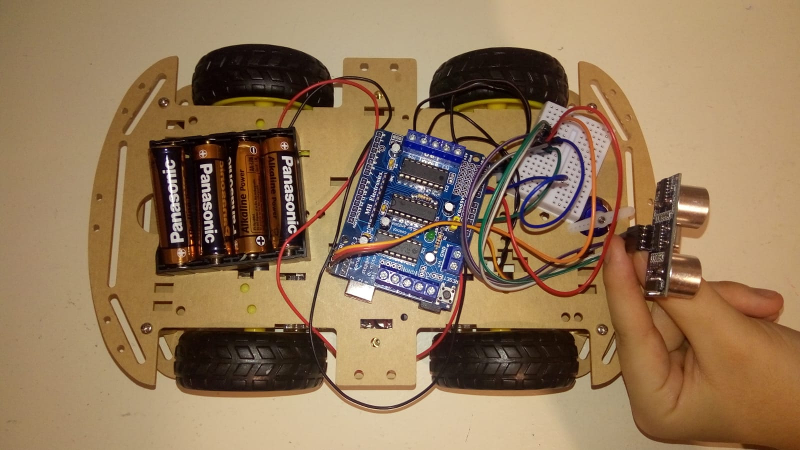
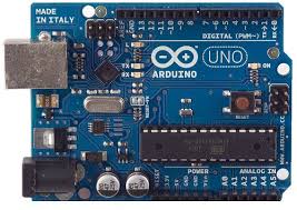
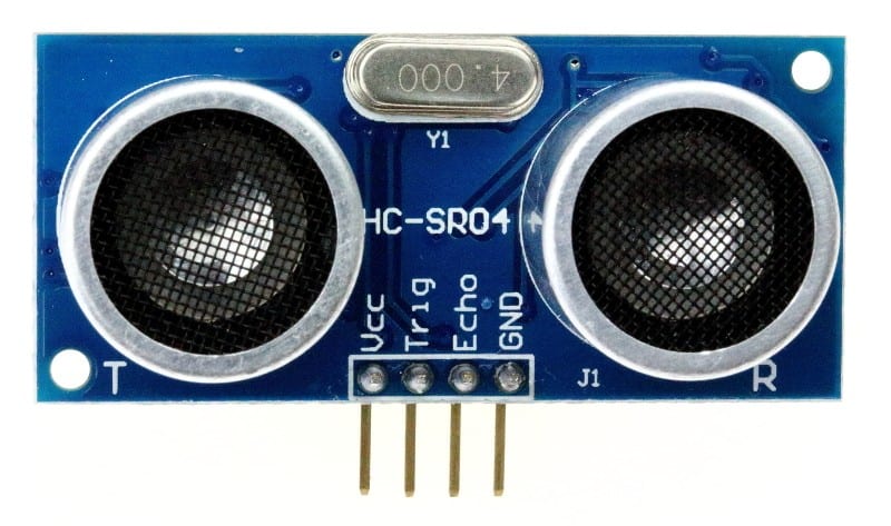
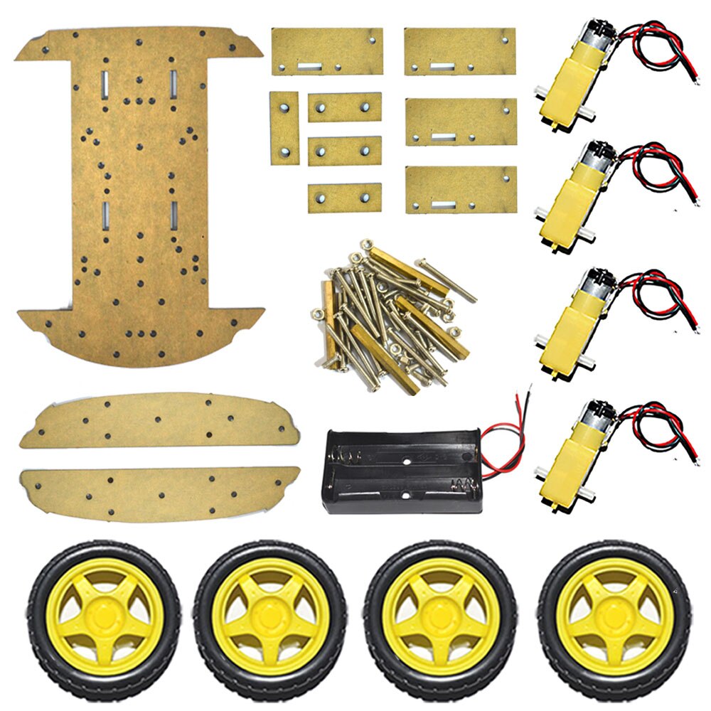
Dans ce projet, on vous montrera comment créer un robot anti-obstacle basé sur Arduino en utilisant un capteur ultrasonique HC-SR04.
On a utiliser le logiciels Arduino pour programmer la carte Arduino.
On a utiliser le logiciels fritzing pour modéliser le schema.
Slides & Videos
Members
| Name | Contribution |
|---|---|
| Amel AIT MOHAND | On a travaillé en binôme sur l'ensemble du projet . On a partagé un lien sur Google doc où on a travaillé au même temps à chaque fois on ajoutait des parties et on les corrigeait ensemble, c’était le cas pour le rapport et le code . Pour la vidéo on l'a faite à la bibliothèque de la fac où à chaque partie l'une faisait l'assemblage et l'autre filmait et vice-versa. |
| Tafsouth AKKOUL | On a travaillé en binôme sur l'ensemble du projet . On a partagé un lien sur Google doc où on a travaillé au même temps à chaque fois on ajoutait des parties et on les corrigeait ensemble, c’était le cas pour le rapport et le code . Pour la vidéo on l'a faite à la bibliothèque de la fac où à chaque partie l'une faisait l'assemblage et l'autre filmait et vice-versa. |
State of the Art
Business Aspect
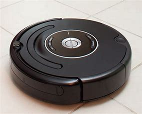
Il existe déjà sur le marché ce type de produit ou du moins des robots qui ont presque le même concept celui de la détection des obstacles à des prix variés. Par exemple, les aspirateurs robots qui sont de plus en plus demandés et qui coûtent peu cher étant donné ce qu’ils font (entre 200 à 600), mais le prix grimpe très vite et le robot aspirateur devient dans certains cas très coûteux, car il peut présenter des fonctionnalités très avancées et qui demandent un travail de plus à réaliser (il peut atteindre jusqu’à 999 euro).
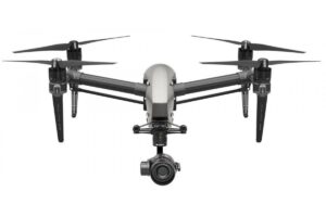
Les drones dotés de capteurs de détection d’obstacles et d’évitement de collision sont de plus en plus répandus dans les secteurs grand public et professionnel.
Cette technologie de détection et d’évitement d’obstacles a commencé avec des capteurs détectant des objets devant le drone. Maintenant, les derniers drones de DJI, Walkera, Yuneec et d’autres ont des capteurs d’évitement d’obstacles avant, arrière, ci-dessous et latéraux.
Avec la détection d’obstacles ainsi que les nombreuses fonctionnalités de sécurité qui équipent les drones aujourd’hui, nous devrions voir beaucoup plus de personnes se lancer dans le drone comme passe-temps ou comme profession. Il y a tant de grandes utilisations pour les drones et encore plus à réaliser.
Les drones sont avec nous pour rester et nous pourrions envisager un avenir où les drones livreraient de manière autonome des colis, des médicaments et de la pizza à nos portes.
Technical Aspect
Project Description
Problem Definition
qui combine à la fois efficacité et rapidité ?
Challenges & Motivation
On a tous ce rêve d'enfant de construire notre propre robot, de le façonner comme on veut, lui ajouter des fonctionnalités différentes.
Alors on a choisi de construire ce type de robot car il nous paraissait d'abord original. En effet, n'importe qui comprendrait de quoi nous parlons si nous évoquions le nom de "robot anti-obstacle", cependant très peu de personnes connaissent son fonctionnement, et surtout comment en faire un.
De plus pour sa capacité à faciliter le quotidien des personnes par exemple au ménage (robot aspirateur), et pourquoi pas dans le future avec quelques modifications un robot qui peut servir de guide pour les personnes aveugles tel que les chiens . Et notamment s'en servir pour des livraisons d'un kilomètre ( comme le robot de l'entreprise CarriRo)
Real and Complete Usecases
En fonction de l’état du capteur et du robot, on choisit la procédure à suivre. Tant qu’il n’y a pas d’obstacle on avance. Si un obstacle se présente, on lance la procédure d’évitement:
- On s’arrête.
- Fait un pas en arrière.
- Il regarde alors ses deux côtés gauche et droit et commence à se déplacer de la meilleure façon possible.
Technical Description
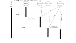
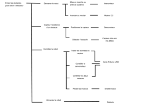
Ça concerne plus les diagrammes qu’on a utilisé pour connaître les mouvements de notre robot et réaliser le code c’est à dire le diagramme de cas d’utilisation et le diagramme séquentiel.
Lorsque notre robot rencontre un obstacle situé à une distance précise pendant qu’il avance, il arrête automatiquement d’avancer et fait un pas en arrière. Il regarde alors ses deux côtés gauche et droit et commence à se déplacer de la meilleure façon possible, c’est-à-dire soit dans la direction de la gauche s’il y a un autre obstacle à droite, soit dans la direction de la droite s’il y a un autre obstacle à gauche.
Le robot qui évite les obstacles est très utile et il est à la base de nombreux grands projets tels que les voitures automatiques, les robots utilisés dans les usines de fabrication, et même les robots utilisés dans les vaisseaux spatiaux.
https://www.aranacorp.com/fr/un-robot-qui-detecte-et-evite-les-obstacles/
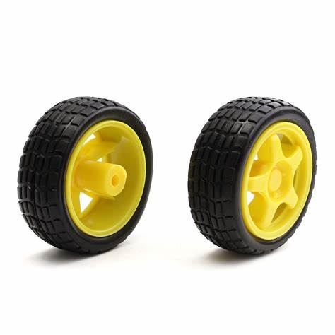
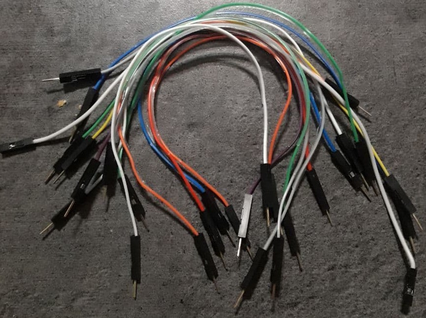
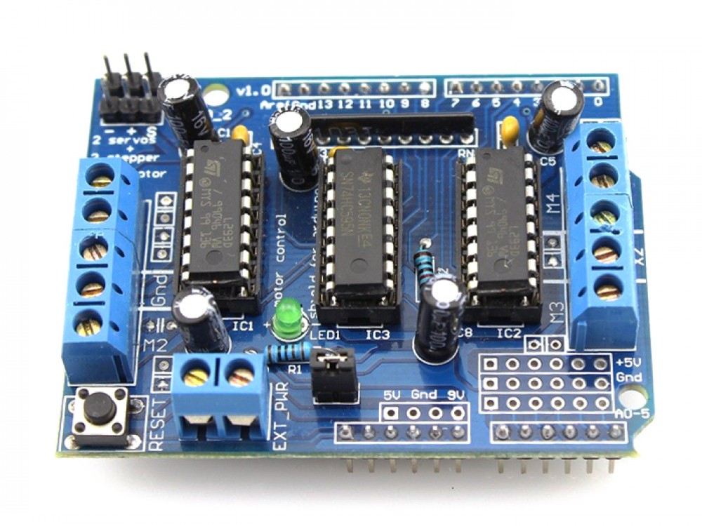
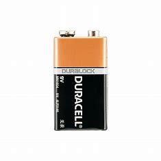
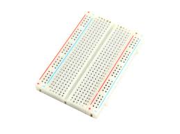
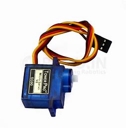
Hardware
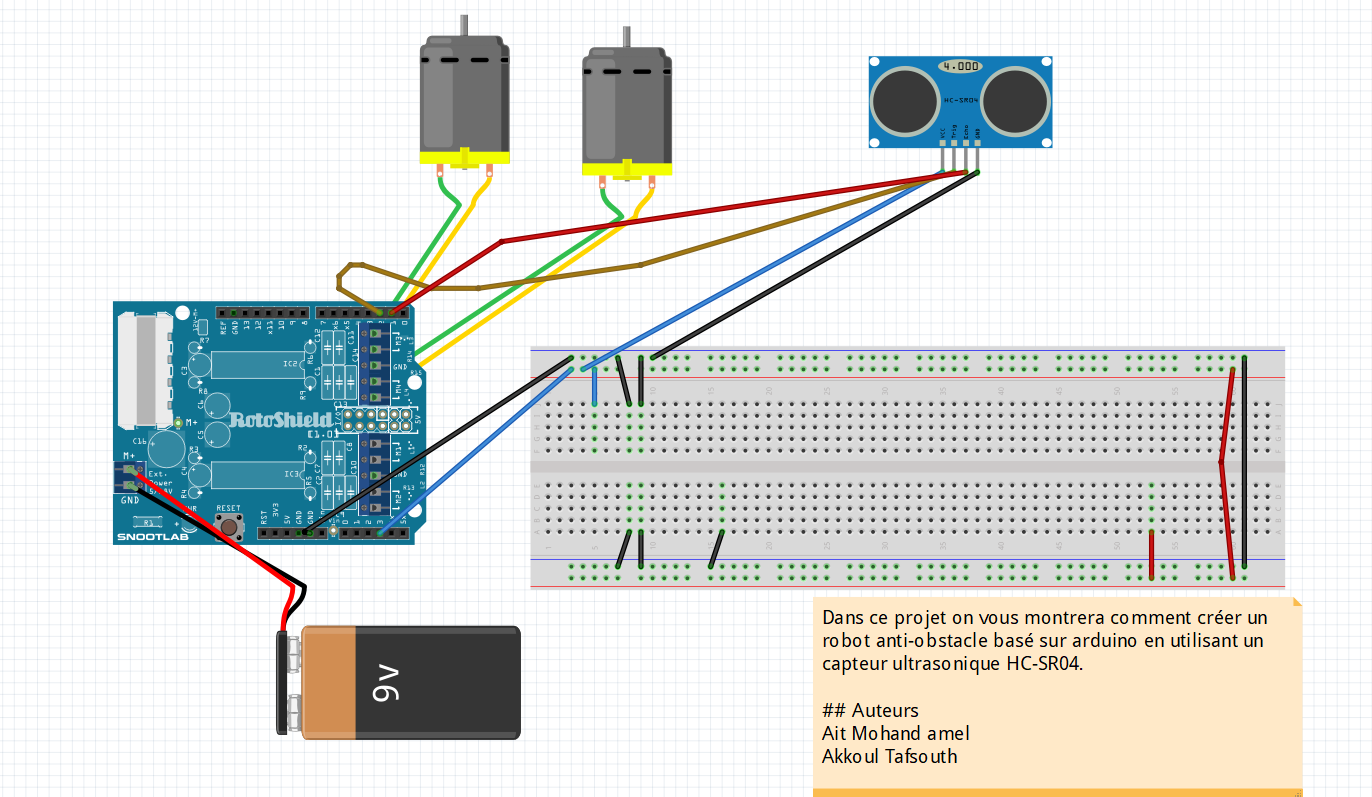
Software
Arduino Code
#include "AFMotor.h" #include#define echopin A2 // echo pin #define trigpin A1 // Trigger pin Servo myservo; const int MOTOR_1 = 1; const int MOTOR_2 = 2; const int MOTOR_3 = 3; const int MOTOR_4 = 4; AF_DCMotor motor1(MOTOR_1, MOTOR12_64KHZ); // create motor object, 64KHz pwm AF_DCMotor motor2(MOTOR_2, MOTOR12_64KHZ); // create motor object, 64KHz pwm AF_DCMotor motor3(MOTOR_3, MOTOR12_64KHZ); // create motor object, 64KHz pwm AF_DCMotor motor4(MOTOR_4, MOTOR12_64KHZ); // create motor object, 64KHz pwm //=============================================================================== // Initialization //=============================================================================== int distance_L, distance_F, distance_R; long distance; int set = 20; void setup() { Serial.begin(9600); // Initialize serial port Serial.println("Start"); myservo.attach(10); myservo.write(90); pinMode (trigpin, OUTPUT); pinMode (echopin, INPUT ); motor1.setSpeed(180); // set the motor speed to 0-255 motor2.setSpeed(180); motor3.setSpeed(180); motor4.setSpeed(180); } //=============================================================================== // Main //=============================================================================== void loop() { distance_F = data(); Serial.print("S="); Serial.println(distance_F); if (distance_F > set){ Serial.println("Forward"); motor1.run(FORWARD); // turn it on going forward motor2.run(FORWARD); motor3.run(FORWARD); motor4.run(FORWARD); } else{hc_sr4();} } long data(){ digitalWrite(trigpin, LOW); delayMicroseconds(2); digitalWrite(trigpin, HIGH); delayMicroseconds(10); distance = pulseIn (echopin, HIGH); return distance / 29 / 2; } void compareDistance(){ if (distance_L > distance_R){ motor1.run(BACKWARD); // turn it on going left motor2.run(BACKWARD); motor3.run(FORWARD); motor4.run(FORWARD); delay(350); } else if (distance_R > distance_L){ motor1.run(FORWARD); // the other right motor2.run(FORWARD); motor3.run(BACKWARD); motor4.run(BACKWARD); delay(350); } else{ motor1.run(BACKWARD); // the other way motor2.run(BACKWARD); motor3.run(BACKWARD); motor4.run(BACKWARD); delay(300); motor1.run(BACKWARD); // turn it on going left motor2.run(BACKWARD); motor3.run(FORWARD); motor4.run(FORWARD); delay(500); } } void hc_sr4(){ Serial.println("Stop"); motor1.run(RELEASE); // stopped motor2.run(RELEASE); motor3.run(RELEASE); motor4.run(RELEASE); myservo.write(0); delay(300); distance_R = data(); delay(100); myservo.write(170); delay(500); distance_L = data(); delay(100); myservo.write(90); delay(300); compareDistance(); }
// Adafruit Motor shield library // copyright Adafruit Industries LLC, 2009 // this code is public domain, enjoy! /* * Usage Notes: * For PIC32, all features work properly with the following two exceptions: * * 1) Because the PIC32 only has 5 PWM outputs, and the AFMotor shield needs 6 * to completely operate (for for motor outputs and two for RC servos), the * M1 motor output will not have PWM ability when used with a PIC32 board. * However, there is a very simple workaround. If you need to drive a stepper * or DC motor with PWM on motor output M1, you can use the PWM output on pin * 9 or pin 10 (normally use for RC servo outputs on Arduino, not needed for * RC servo outputs on PIC32) to drive the PWM input for M1 by simply putting * a jumber from pin 9 to pin 11 or pin 10 to pin 11. Then uncomment one of the * two #defines below to activate the PWM on either pin 9 or pin 10. You will * then have a fully functional microstepping for 2 stepper motors, or four * DC motor outputs with PWM. * * 2) There is a conflict between RC Servo outputs on pins 9 and pins 10 and * the operation of DC motors and stepper motors as of 9/2012. This issue * will get fixed in future MPIDE releases, but at the present time it means * that the Motor Party example will NOT work properly. Any time you attach * an RC servo to pins 9 or pins 10, ALL PWM outputs on the whole board will * stop working. Thus no steppers or DC motors. * */ //09/15/2012 Modified for use with chipKIT boards #ifndef _AFMotor_h_ #define _AFMotor_h_ #include #if defined(__AVR__) #include //#define MOTORDEBUG 1 #define MICROSTEPS 16 // 8 or 16 #define MOTOR12_64KHZ _BV(CS20) // no prescale #define MOTOR12_8KHZ _BV(CS21) // divide by 8 #define MOTOR12_2KHZ _BV(CS21) | _BV(CS20) // divide by 32 #define MOTOR12_1KHZ _BV(CS22) // divide by 64 #define MOTOR34_64KHZ _BV(CS00) // no prescale #define MOTOR34_8KHZ _BV(CS01) // divide by 8 #define MOTOR34_1KHZ _BV(CS01) | _BV(CS00) // divide by 64 #define DC_MOTOR_PWM_RATE MOTOR34_8KHZ // PWM rate for DC motors #define STEPPER1_PWM_RATE MOTOR12_64KHZ // PWM rate for stepper 1 #define STEPPER2_PWM_RATE MOTOR34_64KHZ // PWM rate for stepper 2 #elif defined(__PIC32MX__) //#define MOTORDEBUG 1 // Uncomment the one of following lines if you have put a jumper from // either pin 9 to pin 11 or pin 10 to pin 11 on your Motor Shield. // Either will enable PWM for M1 //#define PIC32_USE_PIN9_FOR_M1_PWM //#define PIC32_USE_PIN10_FOR_M1_PWM #define MICROSTEPS 16 // 8 or 16 // For PIC32 Timers, define prescale settings by PWM frequency #define MOTOR12_312KHZ 0 // 1:1, actual frequency 312KHz #define MOTOR12_156KHZ 1 // 1:2, actual frequency 156KHz #define MOTOR12_64KHZ 2 // 1:4, actual frequency 78KHz #define MOTOR12_39KHZ 3 // 1:8, acutal frequency 39KHz #define MOTOR12_19KHZ 4 // 1:16, actual frequency 19KHz #define MOTOR12_8KHZ 5 // 1:32, actual frequency 9.7KHz #define MOTOR12_4_8KHZ 6 // 1:64, actual frequency 4.8KHz #define MOTOR12_2KHZ 7 // 1:256, actual frequency 1.2KHz #define MOTOR12_1KHZ 7 // 1:256, actual frequency 1.2KHz #define MOTOR34_312KHZ 0 // 1:1, actual frequency 312KHz #define MOTOR34_156KHZ 1 // 1:2, actual frequency 156KHz #define MOTOR34_64KHZ 2 // 1:4, actual frequency 78KHz #define MOTOR34_39KHZ 3 // 1:8, acutal frequency 39KHz #define MOTOR34_19KHZ 4 // 1:16, actual frequency 19KHz #define MOTOR34_8KHZ 5 // 1:32, actual frequency 9.7KHz #define MOTOR34_4_8KHZ 6 // 1:64, actual frequency 4.8KHz #define MOTOR34_2KHZ 7 // 1:256, actual frequency 1.2KHz #define MOTOR34_1KHZ 7 // 1:256, actual frequency 1.2KHz // PWM rate for DC motors. #define DC_MOTOR_PWM_RATE MOTOR34_39KHZ // Note: for PIC32, both of these must be set to the same value // since there's only one timebase for all 4 PWM outputs #define STEPPER1_PWM_RATE MOTOR12_39KHZ #define STEPPER2_PWM_RATE MOTOR34_39KHZ #endif // Bit positions in the 74HCT595 shift register output #define MOTOR1_A 2 #define MOTOR1_B 3 #define MOTOR2_A 1 #define MOTOR2_B 4 #define MOTOR4_A 0 #define MOTOR4_B 6 #define MOTOR3_A 5 #define MOTOR3_B 7 // Constants that the user passes in to the motor calls #define FORWARD 1 #define BACKWARD 2 #define BRAKE 3 #define RELEASE 4 // Constants that the user passes in to the stepper calls #define SINGLE 1 #define DOUBLE 2 #define INTERLEAVE 3 #define MICROSTEP 4 /* #define LATCH 4 #define LATCH_DDR DDRB #define LATCH_PORT PORTB #define CLK_PORT PORTD #define CLK_DDR DDRD #define CLK 4 #define ENABLE_PORT PORTD #define ENABLE_DDR DDRD #define ENABLE 7 #define SER 0 #define SER_DDR DDRB #define SER_PORT PORTB */ // Arduino pin names for interface to 74HCT595 latch #define MOTORLATCH 12 #define MOTORCLK 4 #define MOTORENABLE 7 #define MOTORDATA 8 class AFMotorController { public: AFMotorController(void); void enable(void); friend class AF_DCMotor; void latch_tx(void); uint8_t TimerInitalized; }; class AF_DCMotor { public: AF_DCMotor(uint8_t motornum, uint8_t freq = DC_MOTOR_PWM_RATE); void run(uint8_t); void setSpeed(uint8_t); private: uint8_t motornum, pwmfreq; }; class AF_Stepper { public: AF_Stepper(uint16_t, uint8_t); void step(uint16_t steps, uint8_t dir, uint8_t style = SINGLE); void setSpeed(uint16_t); uint8_t onestep(uint8_t dir, uint8_t style); void release(void); uint16_t revsteps; // # steps per revolution uint8_t steppernum; uint32_t usperstep, steppingcounter; private: uint8_t currentstep; }; uint8_t getlatchstate(void); #endif
// Adafruit Motor shield library
// copyright Adafruit Industries LLC, 2009
// this code is public domain, enjoy!


#if (ARDUINO >= 100)
  #include "Arduino.h"
#else
  #if defined(__AVR__)
    #include
  #endif
  #include "WProgram.h"
#endif

#include "AFMotor.h"


static uint8_t latch_state;

#if (MICROSTEPS == 8)
uint8_t microstepcurve[] = {0, 50, 98, 142, 180, 212, 236, 250, 255};
#elif (MICROSTEPS == 16)
uint8_t microstepcurve[] = {0, 25, 50, 74, 98, 120, 141, 162, 180, 197, 212, 225, 236, 244, 250, 253, 255};
#endif

AFMotorController::AFMotorController(void) {
    TimerInitalized = false;
}

void AFMotorController::enable(void) {
  // setup the latch
  /*
  LATCH_DDR |= _BV(LATCH);
  ENABLE_DDR |= _BV(ENABLE);
  CLK_DDR |= _BV(CLK);
  SER_DDR |= _BV(SER);
  */
  pinMode(MOTORLATCH, OUTPUT);
  pinMode(MOTORENABLE, OUTPUT);
  pinMode(MOTORDATA, OUTPUT);
  pinMode(MOTORCLK, OUTPUT);

  latch_state = 0;

  latch_tx();  // "reset"

  //ENABLE_PORT &= ~_BV(ENABLE); // enable the chip outputs!
  digitalWrite(MOTORENABLE, LOW);
}


void AFMotorController::latch_tx(void) {
  uint8_t i;

  //LATCH_PORT &= ~_BV(LATCH);
  digitalWrite(MOTORLATCH, LOW);

  //SER_PORT &= ~_BV(SER);
  digitalWrite(MOTORDATA, LOW);

  for (i=0; i<8; i++) {
    //CLK_PORT &= ~_BV(CLK);
    digitalWrite(MOTORCLK, LOW);

    if (latch_state & _BV(7-i)) {
      //SER_PORT |= _BV(SER);
      digitalWrite(MOTORDATA, HIGH);
    } else {
      //SER_PORT &= ~_BV(SER);
      digitalWrite(MOTORDATA, LOW);
    }
    //CLK_PORT |= _BV(CLK);
    digitalWrite(MOTORCLK, HIGH);
  }
  //LATCH_PORT |= _BV(LATCH);
  digitalWrite(MOTORLATCH, HIGH);
}

static AFMotorController MC;

/******************************************
               MOTORS
******************************************/
inline void initPWM1(uint8_t freq) {
#if defined(__AVR_ATmega8__) || \
    defined(__AVR_ATmega48__) || \
    defined(__AVR_ATmega88__) || \
    defined(__AVR_ATmega168__) || \
    defined(__AVR_ATmega328P__)
    // use PWM from timer2A on PB3 (Arduino pin #11)
    TCCR2A |= _BV(COM2A1) | _BV(WGM20) | _BV(WGM21); // fast PWM, turn on oc2a
    TCCR2B = freq & 0x7;
    OCR2A = 0;
#elif defined(__AVR_ATmega1280__) || defined(__AVR_ATmega2560__)
    // on arduino mega, pin 11 is now PB5 (OC1A)
    TCCR1A |= _BV(COM1A1) | _BV(WGM10); // fast PWM, turn on oc1a
    TCCR1B = (freq & 0x7) | _BV(WGM12);
    OCR1A = 0;
#elif defined(__PIC32MX__)
    #if defined(PIC32_USE_PIN9_FOR_M1_PWM)
        // Make sure that pin 11 is an input, since we have tied together 9 and 11
        pinMode(9, OUTPUT);
        pinMode(11, INPUT);
        if (!MC.TimerInitalized)
        {   // Set up Timer2 for 80MHz counting fro 0 to 256
            T2CON = 0x8000 | ((freq & 0x07) << 4); // ON=1, FRZ=0, SIDL=0, TGATE=0, TCKPS=, T32=0, TCS=0; // ON=1, FRZ=0, SIDL=0, TGATE=0, TCKPS=0, T32=0, TCS=0
            TMR2 = 0x0000;
            PR2 = 0x0100;
            MC.TimerInitalized = true;
        }
         // Setup OC4 (pin 9) in PWM mode, with Timer2 as timebase
        OC4CON = 0x8006;    // OC32 = 0, OCTSEL=0, OCM=6
        OC4RS = 0x0000;
        OC4R = 0x0000;
    #elif defined(PIC32_USE_PIN10_FOR_M1_PWM)
        // Make sure that pin 11 is an input, since we have tied together 9 and 11
        pinMode(10, OUTPUT);
        pinMode(11, INPUT);
        if (!MC.TimerInitalized)
        {   // Set up Timer2 for 80MHz counting fro 0 to 256
            T2CON = 0x8000 | ((freq & 0x07) << 4); // ON=1, FRZ=0, SIDL=0, TGATE=0, TCKPS=, T32=0, TCS=0; // ON=1, FRZ=0, SIDL=0, TGATE=0, TCKPS=0, T32=0, TCS=0
            TMR2 = 0x0000;
            PR2 = 0x0100;
            MC.TimerInitalized = true;
        }
         // Setup OC5 (pin 10) in PWM mode, with Timer2 as timebase
        OC5CON = 0x8006;    // OC32 = 0, OCTSEL=0, OCM=6
        OC5RS = 0x0000;
        OC5R = 0x0000;
    #else
        // If we are not using PWM for pin 11, then just do digital
        digitalWrite(11, LOW);
    #endif
#else
   #error "This chip is not supported!"
#endif
    #if !defined(PIC32_USE_PIN9_FOR_M1_PWM) && !defined(PIC32_USE_PIN10_FOR_M1_PWM)
        pinMode(11, OUTPUT);
    #endif
}

inline void setPWM1(uint8_t s) {
#if defined(__AVR_ATmega8__) || \
    defined(__AVR_ATmega48__) || \
    defined(__AVR_ATmega88__) || \
    defined(__AVR_ATmega168__) || \
    defined(__AVR_ATmega328P__)
    // use PWM from timer2A on PB3 (Arduino pin #11)
    OCR2A = s;
#elif defined(__AVR_ATmega1280__) || defined(__AVR_ATmega2560__)
    // on arduino mega, pin 11 is now PB5 (OC1A)
    OCR1A = s;
#elif defined(__PIC32MX__)
    #if defined(PIC32_USE_PIN9_FOR_M1_PWM)
        // Set the OC4 (pin 9) PMW duty cycle from 0 to 255
        OC4RS = s;
    #elif defined(PIC32_USE_PIN10_FOR_M1_PWM)
        // Set the OC5 (pin 10) PMW duty cycle from 0 to 255
        OC5RS = s;
    #else
        // If we are not doing PWM output for M1, then just use on/off
        if (s > 127)
        {
            digitalWrite(11, HIGH);
        }
        else
        {
            digitalWrite(11, LOW);
        }
    #endif
#else
   #error "This chip is not supported!"
#endif
}

inline void initPWM2(uint8_t freq) {
#if defined(__AVR_ATmega8__) || \
    defined(__AVR_ATmega48__) || \
    defined(__AVR_ATmega88__) || \
    defined(__AVR_ATmega168__) || \
    defined(__AVR_ATmega328P__)
    // use PWM from timer2B (pin 3)
    TCCR2A |= _BV(COM2B1) | _BV(WGM20) | _BV(WGM21); // fast PWM, turn on oc2b
    TCCR2B = freq & 0x7;
    OCR2B = 0;
#elif defined(__AVR_ATmega1280__) || defined(__AVR_ATmega2560__)
    // on arduino mega, pin 3 is now PE5 (OC3C)
    TCCR3A |= _BV(COM1C1) | _BV(WGM10); // fast PWM, turn on oc3c
    TCCR3B = (freq & 0x7) | _BV(WGM12);
    OCR3C = 0;
#elif defined(__PIC32MX__)
    if (!MC.TimerInitalized)
    {   // Set up Timer2 for 80MHz counting fro 0 to 256
        T2CON = 0x8000 | ((freq & 0x07) << 4); // ON=1, FRZ=0, SIDL=0, TGATE=0, TCKPS=, T32=0, TCS=0; // ON=1, FRZ=0, SIDL=0, TGATE=0, TCKPS=0, T32=0, TCS=0
        TMR2 = 0x0000;
        PR2 = 0x0100;
        MC.TimerInitalized = true;
    }
    // Setup OC1 (pin3) in PWM mode, with Timer2 as timebase
    OC1CON = 0x8006;    // OC32 = 0, OCTSEL=0, OCM=6
    OC1RS = 0x0000;
    OC1R = 0x0000;
#else
   #error "This chip is not supported!"
#endif

    pinMode(3, OUTPUT);
}

inline void setPWM2(uint8_t s) {
#if defined(__AVR_ATmega8__) || \
    defined(__AVR_ATmega48__) || \
    defined(__AVR_ATmega88__) || \
    defined(__AVR_ATmega168__) || \
    defined(__AVR_ATmega328P__)
    // use PWM from timer2A on PB3 (Arduino pin #11)
    OCR2B = s;
#elif defined(__AVR_ATmega1280__) || defined(__AVR_ATmega2560__)
    // on arduino mega, pin 11 is now PB5 (OC1A)
    OCR3C = s;
#elif defined(__PIC32MX__)
    // Set the OC1 (pin3) PMW duty cycle from 0 to 255
    OC1RS = s;
#else
   #error "This chip is not supported!"
#endif
}

inline void initPWM3(uint8_t freq) {
#if defined(__AVR_ATmega8__) || \
    defined(__AVR_ATmega48__) || \
    defined(__AVR_ATmega88__) || \
    defined(__AVR_ATmega168__) || \
    defined(__AVR_ATmega328P__)
    // use PWM from timer0A / PD6 (pin 6)
    TCCR0A |= _BV(COM0A1) | _BV(WGM00) | _BV(WGM01); // fast PWM, turn on OC0A
    //TCCR0B = freq & 0x7;
    OCR0A = 0;
#elif defined(__AVR_ATmega1280__) || defined(__AVR_ATmega2560__)
    // on arduino mega, pin 6 is now PH3 (OC4A)
    TCCR4A |= _BV(COM1A1) | _BV(WGM10); // fast PWM, turn on oc4a
    TCCR4B = (freq & 0x7) | _BV(WGM12);
    //TCCR4B = 1 | _BV(WGM12);
    OCR4A = 0;
#elif defined(__PIC32MX__)
    if (!MC.TimerInitalized)
    {   // Set up Timer2 for 80MHz counting fro 0 to 256
        T2CON = 0x8000 | ((freq & 0x07) << 4); // ON=1, FRZ=0, SIDL=0, TGATE=0, TCKPS=, T32=0, TCS=0; // ON=1, FRZ=0, SIDL=0, TGATE=0, TCKPS=0, T32=0, TCS=0
        TMR2 = 0x0000;
        PR2 = 0x0100;
        MC.TimerInitalized = true;
    }
    // Setup OC3 (pin 6) in PWM mode, with Timer2 as timebase
    OC3CON = 0x8006;    // OC32 = 0, OCTSEL=0, OCM=6
    OC3RS = 0x0000;
    OC3R = 0x0000;
#else
   #error "This chip is not supported!"
#endif
    pinMode(6, OUTPUT);
}

inline void setPWM3(uint8_t s) {
#if defined(__AVR_ATmega8__) || \
    defined(__AVR_ATmega48__) || \
    defined(__AVR_ATmega88__) || \
    defined(__AVR_ATmega168__) || \
    defined(__AVR_ATmega328P__)
    // use PWM from timer0A on PB3 (Arduino pin #6)
    OCR0A = s;
#elif defined(__AVR_ATmega1280__) || defined(__AVR_ATmega2560__)
    // on arduino mega, pin 6 is now PH3 (OC4A)
    OCR4A = s;
#elif defined(__PIC32MX__)
    // Set the OC3 (pin 6) PMW duty cycle from 0 to 255
    OC3RS = s;
#else
   #error "This chip is not supported!"
#endif
}


inline void initPWM4(uint8_t freq) {
#if defined(__AVR_ATmega8__) || \
    defined(__AVR_ATmega48__) || \
    defined(__AVR_ATmega88__) || \
    defined(__AVR_ATmega168__) || \
    defined(__AVR_ATmega328P__)
    // use PWM from timer0B / PD5 (pin 5)
    TCCR0A |= _BV(COM0B1) | _BV(WGM00) | _BV(WGM01); // fast PWM, turn on oc0a
    //TCCR0B = freq & 0x7;
    OCR0B = 0;
#elif defined(__AVR_ATmega1280__) || defined(__AVR_ATmega2560__)
    // on arduino mega, pin 5 is now PE3 (OC3A)
    TCCR3A |= _BV(COM1A1) | _BV(WGM10); // fast PWM, turn on oc3a
    TCCR3B = (freq & 0x7) | _BV(WGM12);
    //TCCR4B = 1 | _BV(WGM12);
    OCR3A = 0;
#elif defined(__PIC32MX__)
    if (!MC.TimerInitalized)
    {   // Set up Timer2 for 80MHz counting fro 0 to 256
        T2CON = 0x8000 | ((freq & 0x07) << 4); // ON=1, FRZ=0, SIDL=0, TGATE=0, TCKPS=, T32=0, TCS=0; // ON=1, FRZ=0, SIDL=0, TGATE=0, TCKPS=0, T32=0, TCS=0
        TMR2 = 0x0000;
        PR2 = 0x0100;
        MC.TimerInitalized = true;
    }
    // Setup OC2 (pin 5) in PWM mode, with Timer2 as timebase
    OC2CON = 0x8006;    // OC32 = 0, OCTSEL=0, OCM=6
    OC2RS = 0x0000;
    OC2R = 0x0000;
#else
   #error "This chip is not supported!"
#endif
    pinMode(5, OUTPUT);
}

inline void setPWM4(uint8_t s) {
#if defined(__AVR_ATmega8__) || \
    defined(__AVR_ATmega48__) || \
    defined(__AVR_ATmega88__) || \
    defined(__AVR_ATmega168__) || \
    defined(__AVR_ATmega328P__)
    // use PWM from timer0A on PB3 (Arduino pin #6)
    OCR0B = s;
#elif defined(__AVR_ATmega1280__) || defined(__AVR_ATmega2560__)
    // on arduino mega, pin 6 is now PH3 (OC4A)
    OCR3A = s;
#elif defined(__PIC32MX__)
    // Set the OC2 (pin 5) PMW duty cycle from 0 to 255
    OC2RS = s;
#else
   #error "This chip is not supported!"
#endif
}

AF_DCMotor::AF_DCMotor(uint8_t num, uint8_t freq) {
  motornum = num;
  pwmfreq = freq;

  MC.enable();

  switch (num) {
  case 1:
    latch_state &= ~_BV(MOTOR1_A) & ~_BV(MOTOR1_B); // set both motor pins to 0
    MC.latch_tx();
    initPWM1(freq);
    break;
  case 2:
    latch_state &= ~_BV(MOTOR2_A) & ~_BV(MOTOR2_B); // set both motor pins to 0
    MC.latch_tx();
    initPWM2(freq);
    break;
  case 3:
    latch_state &= ~_BV(MOTOR3_A) & ~_BV(MOTOR3_B); // set both motor pins to 0
    MC.latch_tx();
    initPWM3(freq);
    break;
  case 4:
    latch_state &= ~_BV(MOTOR4_A) & ~_BV(MOTOR4_B); // set both motor pins to 0
    MC.latch_tx();
    initPWM4(freq);
    break;
  }
}

void AF_DCMotor::run(uint8_t cmd) {
  uint8_t a, b;
  switch (motornum) {
  case 1:
    a = MOTOR1_A; b = MOTOR1_B; break;
  case 2:
    a = MOTOR2_A; b = MOTOR2_B; break;
  case 3:
    a = MOTOR3_A; b = MOTOR3_B; break;
  case 4:
    a = MOTOR4_A; b = MOTOR4_B; break;
  default:
    return;
  }

  switch (cmd) {
  case FORWARD:
    latch_state |= _BV(a);
    latch_state &= ~_BV(b);
    MC.latch_tx();
    break;
  case BACKWARD:
    latch_state &= ~_BV(a);
    latch_state |= _BV(b);
    MC.latch_tx();
    break;
  case RELEASE:
    latch_state &= ~_BV(a);     // A and B both low
    latch_state &= ~_BV(b);
    MC.latch_tx();
    break;
  }
}

void AF_DCMotor::setSpeed(uint8_t speed) {
  switch (motornum) {
  case 1:
    setPWM1(speed); break;
  case 2:
    setPWM2(speed); break;
  case 3:
    setPWM3(speed); break;
  case 4:
    setPWM4(speed); break;
  }
}

/******************************************
               STEPPERS
******************************************/

AF_Stepper::AF_Stepper(uint16_t steps, uint8_t num) {
  MC.enable();

  revsteps = steps;
  steppernum = num;
  currentstep = 0;

  if (steppernum == 1) {
    latch_state &= ~_BV(MOTOR1_A) & ~_BV(MOTOR1_B) &
      ~_BV(MOTOR2_A) & ~_BV(MOTOR2_B); // all motor pins to 0
    MC.latch_tx();

    // enable both H bridges
    pinMode(11, OUTPUT);
    pinMode(3, OUTPUT);
    digitalWrite(11, HIGH);
    digitalWrite(3, HIGH);

    // use PWM for microstepping support
    initPWM1(STEPPER1_PWM_RATE);
    initPWM2(STEPPER1_PWM_RATE);
    setPWM1(255);
    setPWM2(255);

  } else if (steppernum == 2) {
    latch_state &= ~_BV(MOTOR3_A) & ~_BV(MOTOR3_B) &
      ~_BV(MOTOR4_A) & ~_BV(MOTOR4_B); // all motor pins to 0
    MC.latch_tx();

    // enable both H bridges
    pinMode(5, OUTPUT);
    pinMode(6, OUTPUT);
    digitalWrite(5, HIGH);
    digitalWrite(6, HIGH);

    // use PWM for microstepping support
    // use PWM for microstepping support
    initPWM3(STEPPER2_PWM_RATE);
    initPWM4(STEPPER2_PWM_RATE);
    setPWM3(255);
    setPWM4(255);
  }
}

void AF_Stepper::setSpeed(uint16_t rpm) {
  usperstep = 60000000 / ((uint32_t)revsteps * (uint32_t)rpm);
  steppingcounter = 0;
}

void AF_Stepper::release(void) {
  if (steppernum == 1) {
    latch_state &= ~_BV(MOTOR1_A) & ~_BV(MOTOR1_B) &
      ~_BV(MOTOR2_A) & ~_BV(MOTOR2_B); // all motor pins to 0
    MC.latch_tx();
  } else if (steppernum == 2) {
    latch_state &= ~_BV(MOTOR3_A) & ~_BV(MOTOR3_B) &
      ~_BV(MOTOR4_A) & ~_BV(MOTOR4_B); // all motor pins to 0
    MC.latch_tx();
  }
}

void AF_Stepper::step(uint16_t steps, uint8_t dir,  uint8_t style) {
  uint32_t uspers = usperstep;
  uint8_t ret = 0;

  if (style == INTERLEAVE) {
    uspers /= 2;
  }
 else if (style == MICROSTEP) {
    uspers /= MICROSTEPS;
    steps *= MICROSTEPS;
#ifdef MOTORDEBUG
    Serial.print("steps = "); Serial.println(steps, DEC);
#endif
  }

  while (steps--) {
    ret = onestep(dir, style);
    delay(uspers/1000); // in ms
    steppingcounter += (uspers % 1000);
    if (steppingcounter >= 1000) {
      delay(1);
      steppingcounter -= 1000;
    }
  }
  if (style == MICROSTEP) {
    while ((ret != 0) && (ret != MICROSTEPS)) {
      ret = onestep(dir, style);
      delay(uspers/1000); // in ms
      steppingcounter += (uspers % 1000);
      if (steppingcounter >= 1000) {
	delay(1);
	steppingcounter -= 1000;
      }
    }
  }
}

uint8_t AF_Stepper::onestep(uint8_t dir, uint8_t style) {
  uint8_t a, b, c, d;
  uint8_t ocrb, ocra;

  ocra = ocrb = 255;

  if (steppernum == 1) {
    a = _BV(MOTOR1_A);
    b = _BV(MOTOR2_A);
    c = _BV(MOTOR1_B);
    d = _BV(MOTOR2_B);
  } else if (steppernum == 2) {
    a = _BV(MOTOR3_A);
    b = _BV(MOTOR4_A);
    c = _BV(MOTOR3_B);
    d = _BV(MOTOR4_B);
  } else {
    return 0;
  }

  // next determine what sort of stepping procedure we're up to
  if (style == SINGLE) {
    if ((currentstep/(MICROSTEPS/2)) % 2) { // we're at an odd step, weird
      if (dir == FORWARD) {
	currentstep += MICROSTEPS/2;
      }
      else {
	currentstep -= MICROSTEPS/2;
      }
    } else {           // go to the next even step
      if (dir == FORWARD) {
	currentstep += MICROSTEPS;
      }
      else {
	currentstep -= MICROSTEPS;
      }
    }
  } else if (style == DOUBLE) {
    if (! (currentstep/(MICROSTEPS/2) % 2)) { // we're at an even step, weird
      if (dir == FORWARD) {
	currentstep += MICROSTEPS/2;
      } else {
	currentstep -= MICROSTEPS/2;
      }
    } else {           // go to the next odd step
      if (dir == FORWARD) {
	currentstep += MICROSTEPS;
      } else {
	currentstep -= MICROSTEPS;
      }
    }
  } else if (style == INTERLEAVE) {
    if (dir == FORWARD) {
       currentstep += MICROSTEPS/2;
    } else {
       currentstep -= MICROSTEPS/2;
    }
  }

  if (style == MICROSTEP) {
    if (dir == FORWARD) {
      currentstep++;
    } else {
      // BACKWARDS
      currentstep--;
    }

    currentstep += MICROSTEPS*4;
    currentstep %= MICROSTEPS*4;

    ocra = ocrb = 0;
    if ( (currentstep >= 0) && (currentstep < MICROSTEPS)) {
      ocra = microstepcurve[MICROSTEPS - currentstep];
      ocrb = microstepcurve[currentstep];
    } else if  ( (currentstep >= MICROSTEPS) && (currentstep < MICROSTEPS*2)) {
      ocra = microstepcurve[currentstep - MICROSTEPS];
      ocrb = microstepcurve[MICROSTEPS*2 - currentstep];
    } else if  ( (currentstep >= MICROSTEPS*2) && (currentstep < MICROSTEPS*3)) {
      ocra = microstepcurve[MICROSTEPS*3 - currentstep];
      ocrb = microstepcurve[currentstep - MICROSTEPS*2];
    } else if  ( (currentstep >= MICROSTEPS*3) && (currentstep < MICROSTEPS*4)) {
      ocra = microstepcurve[currentstep - MICROSTEPS*3];
      ocrb = microstepcurve[MICROSTEPS*4 - currentstep];
    }
  }

  currentstep += MICROSTEPS*4;
  currentstep %= MICROSTEPS*4;

#ifdef MOTORDEBUG
  Serial.print("current step: "); Serial.println(currentstep, DEC);
  Serial.print(" pwmA = "); Serial.print(ocra, DEC);
  Serial.print(" pwmB = "); Serial.println(ocrb, DEC);
#endif

  if (steppernum == 1) {
    setPWM1(ocra);
    setPWM2(ocrb);
  } else if (steppernum == 2) {
    setPWM3(ocra);
    setPWM4(ocrb);
  }


  // release all
  latch_state &= ~a & ~b & ~c & ~d; // all motor pins to 0

  //Serial.println(step, DEC);
  if (style == MICROSTEP) {
    if ((currentstep >= 0) && (currentstep < MICROSTEPS))
      latch_state |= a | b;
    if ((currentstep >= MICROSTEPS) && (currentstep < MICROSTEPS*2))
      latch_state |= b | c;
    if ((currentstep >= MICROSTEPS*2) && (currentstep < MICROSTEPS*3))
      latch_state |= c | d;
    if ((currentstep >= MICROSTEPS*3) && (currentstep < MICROSTEPS*4))
      latch_state |= d | a;
  } else {
    switch (currentstep/(MICROSTEPS/2)) {
    case 0:
      latch_state |= a; // energize coil 1 only
      break;
    case 1:
      latch_state |= a | b; // energize coil 1+2
      break;
    case 2:
      latch_state |= b; // energize coil 2 only
      break;
    case 3:
      latch_state |= b | c; // energize coil 2+3
      break;
    case 4:
      latch_state |= c; // energize coil 3 only
      break;
    case 5:
      latch_state |= c | d; // energize coil 3+4
      break;
    case 6:
      latch_state |= d; // energize coil 4 only
      break;
    case 7:
      latch_state |= d | a; // energize coil 1+4
      break;
    }
  }
#includeint triggerPin = 21; int echoPin = 12; void setup () { Serial.begin(9600); HCSR04.begin(triggerPin, echoPin); } void loop () { double* distances = HCSR04.measureDistanceCm(); Serial.print("1: "); Serial.print(distances[0]); Serial.println("cm"); Serial.println("---"); delay(500); }
/*
  Servo.h - Interrupt driven Servo library for Arduino using 16 bit timers- Version 2
  Copyright (c) 2009 Michael Margolis.  All right reserved.
  This library is free software; you can redistribute it and/or
  modify it under the terms of the GNU Lesser General Public
  License as published by the Free Software Foundation; either
  version 2.1 of the License, or (at your option) any later version.
  This library is distributed in the hope that it will be useful,
  but WITHOUT ANY WARRANTY; without even the implied warranty of
  MERCHANTABILITY or FITNESS FOR A PARTICULAR PURPOSE.  See the GNU
  Lesser General Public License for more details.
  You should have received a copy of the GNU Lesser General Public
  License along with this library; if not, write to the Free Software
  Foundation, Inc., 51 Franklin St, Fifth Floor, Boston, MA  02110-1301  USA
*/

/*
  A servo is activated by creating an instance of the Servo class passing
  the desired pin to the attach() method.
  The servos are pulsed in the background using the value most recently
  written using the write() method.
  Note that analogWrite of PWM on pins associated with the timer are
  disabled when the first servo is attached.
  Timers are seized as needed in groups of 12 servos - 24 servos use two
  timers, 48 servos will use four.
  The sequence used to sieze timers is defined in timers.h
  The methods are:
    Servo - Class for manipulating servo motors connected to Arduino pins.
    attach(pin )  - Attaches a servo motor to an i/o pin.
    attach(pin, min, max  ) - Attaches to a pin setting min and max values in microseconds
    default min is 544, max is 2400

    write()     - Sets the servo angle in degrees.  (invalid angle that is valid as pulse in microseconds is treated as microseconds)
    writeMicroseconds() - Sets the servo pulse width in microseconds
    read()      - Gets the last written servo pulse width as an angle between 0 and 180.
    readMicroseconds()   - Gets the last written servo pulse width in microseconds. (was read_us() in first release)
    attached()  - Returns true if there is a servo attached.
    detach()    - Stops an attached servos from pulsing its i/o pin.
 */

#ifndef Servo_h
#define Servo_h

#include

/*
 * Defines for 16 bit timers used with  Servo library
 *
 * If _useTimerX is defined then TimerX is a 16 bit timer on the current board
 * timer16_Sequence_t enumerates the sequence that the timers should be allocated
 * _Nbr_16timers indicates how many 16 bit timers are available.
 */

// Architecture specific include
#if defined(ARDUINO_ARCH_AVR)
#include "avr/ServoTimers.h"
#elif defined(ARDUINO_ARCH_SAM)
#include "sam/ServoTimers.h"
#elif defined(ARDUINO_ARCH_SAMD)
#include "samd/ServoTimers.h"
#elif defined(ARDUINO_ARCH_STM32F4)
#include "stm32f4/ServoTimers.h"
#elif defined(ARDUINO_ARCH_NRF52)
#include "nrf52/ServoTimers.h"
#elif defined(ARDUINO_ARCH_MEGAAVR)
#include "megaavr/ServoTimers.h"
#elif defined(ARDUINO_ARCH_MBED)
#include "mbed/ServoTimers.h"
#else
#error "This library only supports boards with an AVR, SAM, SAMD, NRF52 or STM32F4 processor."
#endif

#define Servo_VERSION           2     // software version of this library

#define MIN_PULSE_WIDTH       544     // the shortest pulse sent to a servo
#define MAX_PULSE_WIDTH      2400     // the longest pulse sent to a servo
#define DEFAULT_PULSE_WIDTH  1500     // default pulse width when servo is attached
#define REFRESH_INTERVAL    20000     // minumim time to refresh servos in microseconds

#define SERVOS_PER_TIMER       12     // the maximum number of servos controlled by one timer
#define MAX_SERVOS   (_Nbr_16timers  * SERVOS_PER_TIMER)

#define INVALID_SERVO         255     // flag indicating an invalid servo index

#if !defined(ARDUINO_ARCH_STM32F4)

typedef struct  {
  uint8_t nbr        :6 ;             // a pin number from 0 to 63
  uint8_t isActive   :1 ;             // true if this channel is enabled, pin not pulsed if false
} ServoPin_t   ;

typedef struct {
  ServoPin_t Pin;
  volatile unsigned int ticks;
} servo_t;

class Servo
{
public:
  Servo();
  uint8_t attach(int pin);           // attach the given pin to the next free channel, sets pinMode, returns channel number or 0 if failure
  uint8_t attach(int pin, int min, int max); // as above but also sets min and max values for writes.
  void detach();
  void write(int value);             // if value is < 200 its treated as an angle, otherwise as pulse width in microseconds
  void writeMicroseconds(int value); // Write pulse width in microseconds
  int read();                        // returns current pulse width as an angle between 0 and 180 degrees
  int readMicroseconds();            // returns current pulse width in microseconds for this servo (was read_us() in first release)
  bool attached();                   // return true if this servo is attached, otherwise false
private:
   uint8_t servoIndex;               // index into the channel data for this servo
   int8_t min;                       // minimum is this value times 4 added to MIN_PULSE_WIDTH
   int8_t max;                       // maximum is this value times 4 added to MAX_PULSE_WIDTH
};

#endif
#endif